Now let us take a look at how the functional CPU (FunCPU for short) can be programmed in reality, from the programmer’s point of view.
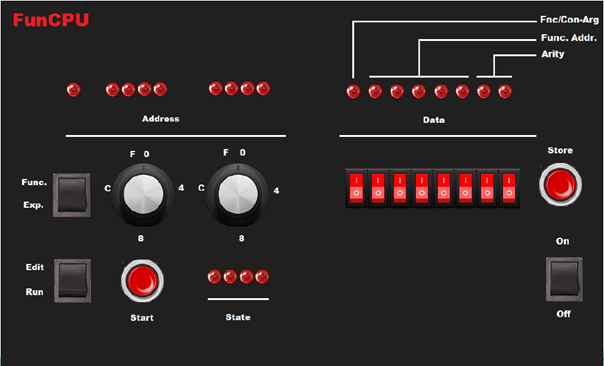
This will be covered by looking at each gizmo (i.e. button, switch, LED, etc.) on the front/control panel.
On the bottom right side, the purpose of the power switch is self explanatory.
On the bottom left side, the switch is used to select between run and edit mode. In edit mode, the functions and/or expressions can be entered/modified/displayed. The computation can be initiated by pressing start button, only when the edit-run switch is turned to run mode.
The third switch is provided to switch between editing functions and expressions.
The two rotary switches next to it, are used to enter the 8-bit physical address in hexadecimal mode. The current physical address (both in edit or run modes) are indicated by the 9 address indicator LEDs. The most significant, the 9th bit LED is on, when expressions are edited in edit mode, or when in run mode the expression symbol is selected by the CPU.
Similarly, the current data byte stored at the actual address is displayed by the LEDs labelled Data. Under these LEDs the eight switches are provided to enter or modify data in binary mode.
Store button (only working in edit mode) is actually used to enter the 8 bit value in either to function memory or expression memory depending on the position of the Func/Exp switch. When the store button is released, the previous data byte displayed by the 8 data LEDs, is overwritten, and the new value is displayed.
The most significant bit (8) denotes whether the value is a function (LED is on) or a constant (or possibly an argument) (LED is off). The following 5 LEDs as suggested by their corresponding label give the physical address of the user-function. The actual address can be obtained by multiplying this 5 bit value by 8 (or simply shifting it left three times). The last two LEDs encode the arity of a user-defined function: 00 , 01, 10, 11 represent arity 4, 3, 2 and 1 respectively.
Finally, some important values in binary form:
- 0000 0000 – zero
- 0111 11xx – argument 1, 2, 3 or 4 (in function mode)
- 1111 1100 – dec function
- 1111 1101 – if function
- 1111 1110 – inc function
- 1xxx xxaa – user-defined function at address %xxxx x000 with arity aa, provided that it is different from the code of the 3 built-in functions described above
- 1111 1111 – end of expression / function
Current machine state is indicated by the four LEDs labelled as State. The initial, starting state is 0000, whereas 1111 denotes the succesfull termination of the computation. In the latter case, the result of the computation is displayed by the data LEDs in binary model.